EN
EN

Micro Weighing Sensors in the Medical Device Industry: In-Depth Research
2026/08/19
Explore the role of micro weighing sensors in the medical device industry and their impact on precision and reliability.
2026/08/13
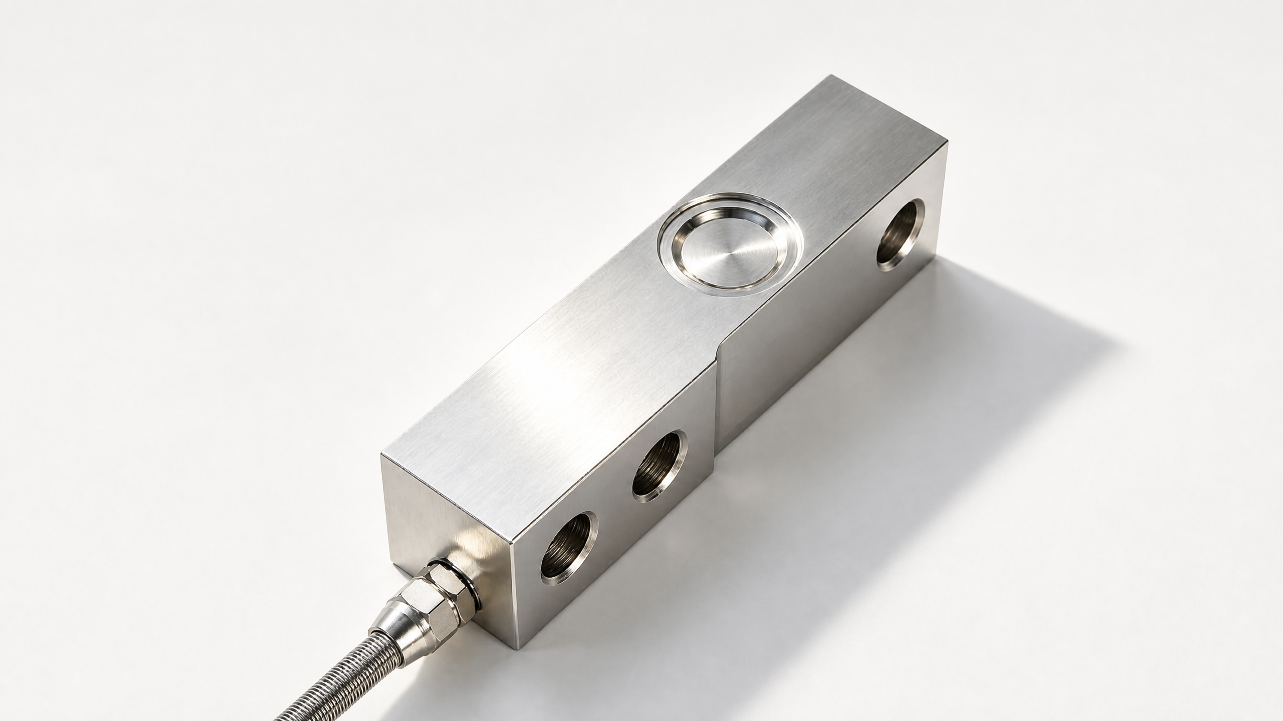
A cantilever beam load cell is essentially an elastic metal beam fixed at one end and free at the other. It mainly consists of the following components:
1. Elastic Body (Sensitive Beam)
● Material: Typically uses 40CrNiMoA alloy steel or 17-4PH stainless steel, offering excellent elasticity and fatigue resistance.
● Shape: Rectangular block or a stepped beam with a variable cross-section, generally ranging from 50 to 300mm in length.
● Key Design: The middle section of the beam usually features a thinned area (strain zone) to concentrate deformation, thereby improving sensitivity.
● Fixed End: Rigidly mounted to the base using 2 to 4 bolts.
● Loading End: Features a loading head (steel ball or pressing head) on top, through which the load is applied vertically to the beam end.
2. Resistance Strain Gauges
Typically, 4 strain gauges are used to form a full Wheatstone bridge.
Mounting Positions:
● 2 gauges mounted on the top surface of the beam (tension zone).
● 2 gauges mounted on the bottom surface of the beam (compression zone).
● Alternatively, they can be mounted near the neutral axis on the side of the beam (shear mode), which provides stronger resistance to off-center loads.
● The nominal resistance is usually 350Ω, though 120Ω and 700Ω specifications are also available.
● The grid length is generally between 1mm and 6mm, selected based on the beam dimensions.
3. Compensation and Sealing
Contains internal temperature compensation resistors (for zero compensation and sensitivity compensation).
Utilizes welded sealing or adhesive sealing, achieving protection ratings of IP67 or IP68.
Cable Options: Direct-exit cable or connector (e.g., M12 aviation plug).
| Parameter | Typical Value | Description |
| Capacity | 5kg ~ 5t | Common: 100kg, 500kg, 1t, 2t |
| Rated Output | 2.0 ± 0.002 mV/V | Output sensitivity at full scale |
| Combined Accuracy | Class C3 (±0.02%) | Also available in C2, C4, C5 classes |
| Input Impedance | 380 ± 10Ω | 350Ω Strain Gauge + Compensation Resistor |
| Output Impedance | 350 ± 3Ω | |
| Excitation Voltage | 5~15V DC | Recommended 10V |
| Insulation Resistance | ≥5000MΩ | At 50V DC |
| Safe Overload | 150% F.S. | Maximum load without damage |
| Ultimate Overload | 200% F.S. | May cause permanent deformation |
| Operating Temperature | -30 ~ +70°C | Compensation range -10~+40°C |
| Creep | ±0.03% F.S./30min | Output drift under constant load |
| Zero Temp. Coefficient | ±0.002% F.S./°C |
Proper Installation Methods
The fixed end must be rigidly secured, with the mounting surface flatness ≤0.05mm.
Point contact or line contact should be maintained between the loading head and the weighed object to avoid lateral forces.
Cables should be properly secured and routed to prevent signal interference caused by swinging.
When multiple sensors are used in parallel (e.g., a 4-corner platform scale), it is essential to ensure uniform load distribution across all sensors.
Common Sources of Error
● Off-center Load Error: Loads deviating from the loading point introduce additional bending moments, causing reading deviations.
● Lateral Force / Torsion: Cantilever beams are sensitive to lateral forces; improper installation can cause zero drift.
● Temperature Effects: Ambient temperature changes lead to zero and sensitivity drift.
● Creep: Slow output changes under prolonged full-load conditions.
● Mechanical Vibration: Shock absorbers or digital filtering are required in dynamic environments.
| Type | Capacity Range | Accuracy | Anti-eccentric Load | Cost | Typical Applications |
| Cantilever Beam | Low-Medium | High | Average | Low | Platform scales, Hoppers |
| Spoke Type | Medium-High | High | Good | Medium | Testing machines, Presses |
| Column Type | High | Medium | Poor | Medium | Truck scales, Silos |
| S-Type (Tension/Compression) | Low-Medium | High | Average | Low | Crane scales, Force testing |
| Single Point (Parallel Beam) | Low | High | Good | Low | Electronic scales, Counting scales |
A 1-ton platform scale typically uses 4 cantilever beam load cells arranged at the four corners:
Capacity per Sensor: 500kg each (4 × 500kg = 2t total, leaving a 50% safety margin).
● The 4 sensors are wired in parallel, with signals aggregated into a junction box.
● Adjustable potentiometers inside the junction box are used for corner error correction.
● The output is fed into a weighing indicator, which displays the weight after A/D conversion and calibration.
Calibration Process: Zero setting under no load → Apply standard test weights → Input the weight value → The indicator automatically calculates the calibration coefficient.

2026/08/19
Explore the role of micro weighing sensors in the medical device industry and their impact on precision and reliability.

2026/08/10
Learn how to efficiently install a weighing sensor on your silo for accurate measurement and monitoring.
Get in touch for customized load cell & linear sensor solutions, technical testing support, or global wholesale cooperation.
Tel
Address
No. 1 Tianfu Road, Zhanggong District, Ganzhou City, Jiangxi Province, China